

Recently, many of our clients and partners in renewable energy sectors, electric vehicle infrastructure, and smart grid development have approached us with identical questions: “What exactly is the working principle of a Solid State Transformer (SST)? How does it genuinely differ from the conventional transformers we install every day, and is it ready to replace them?”
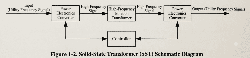
It is an excellent and timely inquiry. To many infrastructure developers and electrical engineers, terms like “solid-state” and “power electronics” sound overly complex or purely theoretical. However, while a Solid State Transformer performs the identical fundamental task as a conventional copper-and-iron transformer—converting voltage to manage electrical power safely—it executes this process with microscopic, digital precision. The underlying architecture relies on a highly logical, three-stage process. Let us break it down using direct, practical engineering terms.
Step 1: Straightening the Line – Converting AC to DC (Rectification)
The power grid natively delivers standard alternating current (AC) at a low frequency of 50Hz or 60Hz. While this incoming voltage is highly stable under normal operating circumstances, its direction reverses continuously, behaving much like a heavy pendulum swinging back and forth.
The very first action an SST takes is to stabilize this shifting power. By utilizing high-power semiconductor rectification modules—increasingly built using modern Silicon Carbide (SiC) wide-bandgap devices—the system converts the fluctuating utility frequency alternating current into a steady, unidirectional direct current (DC).
Think of this initial stage as directing a turbulent, winding river into a perfectly straight, engineered pipeline. Once the electricity is locked into a steady DC state, it becomes significantly easier to manipulate, filter, and balance against external grid fluctuations.
Step 2: Shrinking the Footprint – Achieving High-Frequency Isolation (DC → High-Frequency AC → DC)
This stage represents the technological core of the Solid State Transformer. Because direct current cannot inherently undergo voltage step-down or step-up via magnetic induction, the SST must execute a sophisticated conversion trick.
The newly stabilized DC voltage is passed directly into a high-speed inverter circuit, which chops the continuous current into ultra-high-frequency alternating current, typically ranging between 8 kHz and 20 kHz or even higher. This high-frequency AC is then fed immediately through a specialized high-frequency isolation transformer to achieve the required voltage step-down along with complete galvanic isolation.
- Why is this high-frequency transformation such a breakthrough?In electromagnetic design, the required physical volume and weight of a transformer core are strictly inversely proportional to its operating frequency. Traditional 50Hz/60Hz distribution transformers must rely on massive, heavy stacks of silicon steel sheets and hundreds of kilograms of copper windings to prevent core saturation.By elevating the operating frequency by a factor of several hundred, the physical core inside an SST can be shrunk down to a fraction of its original scale. This drastic frequency leap is the exact reason why solid-state units can achieve an overall physical volume and weight reduction of 60% to 90% compared to traditional substation units. It is the ultimate secret behind the system’s lightweight, high-density characteristics.
Step 3: Custom Delivery – Outputting Tailored AC or DC Power
Once the high-frequency transformer steps down the voltage, the electricity is rectified once more back into a localized, low-voltage DC busbar. At this stage, the SST acts as a universal power interface, distributing electricity based entirely on what the end-use asset demands:
- For Standard Industrial Facilities and Local Grids: The internal system routes power through an output inverter, turning the DC back into standard 220V/380V alternating current with a flawless sine wave.
- For Modern Green Energy Infrastructure: The system completely bypasses the final AC conversion step, feeding highly stable DC power directly to solar energy storage systems, EV ultra-fast charging stations, or enterprise data center server racks (common standards like ±375V or 800V DC architectures).
Because every millisecond of this process is micro-managed by digital signal controllers (DSCs), the SST does not merely alter voltage. It acts as an active power quality management center—instantly stabilizing voltage drops, filtering out harmful line harmonics, facilitating bi-directional power flow, and isolating circuit faults within milliseconds.
SST vs. Conventional Transformers: A Head-to-Head Comparison
| Performance Metric | Conventional Transformers (Oil/Dry-Type) | Solid State Transformers (SST) |
| Core Operational Mode | Passive electromagnetic induction. Responds blindly to grid conditions. | Active electronic switching. Constantly adjusts parameters in real-time. |
| Output Versatility | Strictly limited to a single, fixed AC output profile. | Highly flexible. Capable of simultaneous AC and DC outputs. |
| Power Quality Management | Passes grid harmonics and voltage sags directly through to the load. | Features native filtering, harmonic isolation, and dynamic voltage regulation. |
| Physical Footprint | Inherently large, heavy, and bulky due to material physics. | Highly compact and lightweight, reducing structural volume by up to 70%+. |
| Grid Intelligence | Entirely analog. Requires external sensors for telemetry. | Fully digital natively. Supports remote power scheduling and smart grid integrations. |
Is It Time for Your Project to Adopt Solid State Technology?
Despite these monumental technical advantages, it is vital to remain pragmatic about actual deployment timelines. Solid State Transformers represent an incredible evolutionary step for power grids, but they remain primarily in advanced demonstration and specialized industrial phases. They are highly ideal for rolling stock locomotive traction, localized microgrids (such as isolated island or border outposts), data centers utilizing pure DC buses, and integrated solar-plus-storage charging hubs.
However, for everyday commercial real estate, standard industrial manufacturing zones, and typical residential utility distribution networks, transitioning to SST hardware is currently unnecessary. The acquisition cost remains roughly 3 to 5 times higher than standard units, the maintenance workflows require specialized power electronics engineers, and comprehensive international utility standards are still being codified.
A Professional Perspective from FIJ TECH:
As an established manufacturer specializing in heavy-duty engineering solutions, we advise looking closely at your project’s precise operational requirements rather than chasing technological trends. If your infrastructure does not strictly demand active harmonic filtering, complex DC bus distribution, or critical weight limitations, traditional grid-tied units remain the absolute gold standard for reliability and economic sense.
Modern high-efficiency infrastructure solutions, such as S22-rated energy-conserving Oil-Immersed Transformers or structurally rugged Cast Resin Dry-Type Transformers, continue to deliver the most cost-effective, durable, and highly dependable performance for standard distribution networks. They boast decades of proven operational lifetimes with minimal maintenance overhead, ensuring your capital expenditures translate directly into reliable power delivery.