
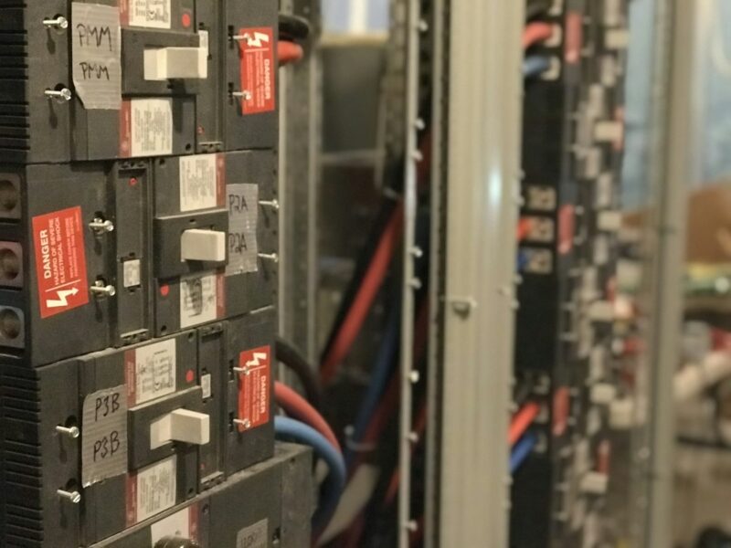
Switchgear is the control and protection heart of any electrical distribution system. For overseas electrical engineers, procurement managers, EPC contractors, and utility buyers, selecting the right switchgear is not just about meeting a specification—it directly impacts project safety, reliability, and total cost of ownership. This comprehensive buying guide from FIJ TECH, a transformer manufacturer with decades of export experience, walks you through every critical decision: from voltage class and insulation type to breaking capacity, protection schemes, and seamless integration with power transformers. Whether you are upgrading a textile mill in Vietnam or building a new substation in the Middle East, the principles here will help you specify switchgear that performs reliably for decades.
Quick Answer / Executive Summary
Selecting switchgear requires matching voltage class, short-circuit breaking capacity, and insulation type (AIS or GIS) to your system fault level and environmental constraints. Always verify transformer impedance to ensure coordination, and specify at least 25% margin above calculated fault current. FIJ TECH supports your project with IEC-compliant transformers and expert guidance for a fully integrated solution.
What Is Switchgear and Why It Matters in Power Distribution
Switchgear is a general term covering the combination of electrical disconnect switches, fuses or circuit breakers, and protective relays used to control, protect, and isolate electrical equipment. In medium voltage (MV) applications—typically 1 kV to 36 kV—switchgear ensures that faults are cleared rapidly, minimizing damage to transformers, cables, and downstream equipment. Without properly specified switchgear, a single fault can cascade into a plant-wide outage, costing thousands of dollars per hour in lost production.
Modern switchgear must also accommodate the increasing complexity of distributed generation, renewable energy integration, and smart grid requirements. For B2B buyers, the key is to balance capital cost with operational reliability and future expandability. This guide focuses on MV switchgear, but the principles apply across LV and HV as well.
Switchgear Selection Decision Tree
Use this step-by-step decision tree to narrow down your switchgear requirements before engaging suppliers. It ensures you cover all critical parameters and avoid costly over- or under-specification.
- Determine system voltage: Identify whether your installation is 0.4 kV (LV), 10–12 kV (MV), or 110 kV+ (HV). This sets the fundamental class of switchgear.
- Calculate maximum short-circuit current at the installation point using the utility fault level and transformer impedance. This value drives the breaking capacity requirement.
- Choose insulation type: Air Insulated Switchgear (AIS) for outdoor or open spaces; Gas Insulated Switchgear (GIS) for compact indoor or urban substations where space is limited.
- Select breaking capacity with at least a 25% margin above the calculated fault current to account for future system growth and transient conditions.
- Determine protection scheme: Define CT/VT ratios, relay types (overcurrent, differential, arc-flash), and coordination with upstream and downstream devices.
- Evaluate future expansion: Specify spare feeders, extendable busbars, and digital monitoring readiness to avoid costly retrofits later.
Switchgear Voltage Classes and Applications
The following table summarizes the common voltage classes, typical switchgear types, applications, and breaking capacities. Use it as a quick reference when defining your technical specification.
| Voltage Class | Common Type | Applications | Breaking Capacity |
|---|---|---|---|
| 0.4 kV | LV switchboard | Final distribution, motor control | 25-100 kA |
| 10-12 kV | MV switchgear (AIS) | Primary distribution, substations | 20-40 kA |
| 24-36 kV | MV switchgear (AIS/GIS) | Industrial substations, utilities | 25-40 kA |
| 110-220 kV | HV switchyard | Transmission, grid connection | 40-63 kA |
For MV applications, AIS remains the most cost-effective choice for outdoor installations with adequate space. GIS, while more expensive, is indispensable in urban substations or offshore platforms where footprint and environmental protection are critical. Always confirm that the selected switchgear complies with relevant standards such as IEC 62271 for MV switchgear and IEEE C37.20 for metal-clad switchgear.
Key Technical Parameters for Switchgear Selection
Beyond voltage and breaking capacity, several parameters influence switchgear performance and longevity. Pay close attention to these:
- Rated current: Continuous current rating must exceed the maximum expected load, typically 630 A, 1250 A, 2000 A, or 3150 A for MV.
- Short-time withstand current: The rms current the switchgear can carry for a specified duration (e.g., 25 kA for 3 seconds).
- Peak withstand current: The peak value of the first major loop of fault current, usually 2.5 times the short-time withstand current.
- Protection degree: IP ratings for indoor (IP4X) or outdoor (IP54 or higher) installations.
- Operating mechanism: Manual, motorized, or spring-charged, depending on automation requirements.
- Standards compliance: IEC 62271, IEEE C37.20, GB/T 3906, and CE marking for European projects.
When integrating with transformers, ensure that the switchgear’s rated voltage and insulation level match the transformer’s primary voltage. FIJ TECH offers a range of oil-immersed transformers and dry-type transformers designed for seamless coordination with MV switchgear.
Voltage Drop & Short-Circuit Impedance Check
One of the most overlooked aspects of switchgear selection is verifying that the transformer’s impedance voltage (uk%) aligns with the switchgear’s breaking capacity and that voltage drop under load remains acceptable. Follow this calculation example:
- Verify transformer impedance voltage (uk%) matches switchgear breaking capacity. The transformer’s uk% determines the maximum short-circuit current available at the switchgear terminals.
- Typical 10kV distribution transformer: uk = 4%. This means that at full load, the voltage drop due to transformer impedance is approximately 4% of rated voltage.
- Calculate voltage drop under load: ΔU = β × uk × (cosφ + sinφ × tanθ), where β is the load factor, cosφ is the power factor, and θ is the phase angle between voltage and current.
- Ensure voltage drop at full load stays below 5% at motor terminals. Exceeding this can cause motor overheating, reduced torque, and nuisance tripping.
For a 10kV system with a 2000 kVA transformer (uk = 4%), the short-circuit current at the LV side is approximately 28 kA. The MV switchgear must have a breaking capacity of at least 35 kA (25% margin). FIJ TECH’s S13 and S22 series transformers are designed with standardized impedances to simplify this coordination.
Installation and Commissioning Checklist for Switchgear
Proper installation and commissioning are critical to ensuring switchgear reliability and safety. Use this checklist to verify each stage:
- Foundation: Level concrete pad, embedment bolts per drawing, clearances for breaker withdrawal (≥1000 mm front, ≥800 mm rear).
- Busbar connections: Clean contact surfaces, apply conductive grease, torque to manufacturer’s specification, verify with micro-ohmmeter.
- Cable termination: Stress-relief kits installed per IEC 61442, correct phase sequence, earth continuity verified.
- Interlock testing: Verify mechanical and electrical interlocks function under simulated fault conditions.
- Primary injection test: Confirm CT ratios and protection relay coordination at 10-20% of rated current.
- Vacuum bottle check: With breaker open, apply 28-38 kV test voltage across contacts to verify integrity.
Always refer to the manufacturer’s installation manual and local codes. For projects in Europe, CE marking and compliance with VDE standards may be required. FIJ TECH provides detailed documentation and support for all our transformers, ensuring smooth integration with your switchgear.
Factory Case Study: 11kV S13 Oil Immersed Distribution Transformer for Southeast Asia Textile Mill
In Vietnam, a textile manufacturing plant faced frequent voltage fluctuations and high no-load losses from its aging S9 transformers. The plant’s management sought a reliable, energy-efficient solution to reduce operational costs and improve power quality.
Challenge: The existing S9 transformers (11kV/0.4kV, 2000kVA) had high no-load losses, contributing to excessive energy bills and voltage instability that affected sensitive textile machinery.
Solution: FIJ TECH supplied an S13-M-2000/11 oil-immersed transformer (11kV/0.4kV, 2000kVA) with advanced energy-efficient design. The S13 series reduces no-load loss by approximately 30% compared to S9, thanks to optimized core materials and improved manufacturing processes. The transformer meets IEC 60076, GB 1094, and ISO 9001 standards.
Result: After upgrading to the S13 transformer, the mill reported a monthly energy cost reduction of approximately 18%. The delivery was completed within 35 days, minimizing downtime. The customer quote: “After upgrading to S13 transformers, our monthly energy cost dropped by approximately 18%. The delivery was completed within 35 days.”
This case demonstrates how selecting the right transformer—coordinated with existing switchgear—can deliver rapid ROI. For similar projects, explore FIJ TECH’s S13 Series 3 Phase Oil-Immersed Power Transformer and S22 Type Energy Efficiency Primary Oil Immersed Transformer.
Common Mistakes to Avoid
Even experienced engineers can overlook critical details when specifying switchgear. Avoid these common pitfalls:
- Underestimating fault current: Failing to account for future system growth or utility fault level changes can lead to switchgear with inadequate breaking capacity.
- Ignoring transformer impedance: Mismatched impedance between transformer and switchgear can cause coordination failures or excessive voltage drop.
- Overlooking environmental conditions: Humidity, altitude, and ambient temperature affect insulation and cooling; specify accordingly.
- Insufficient spare capacity: Not planning for spare feeders or extendable busbars can force expensive retrofits later.
- Skipping commissioning tests: Rushing commissioning without primary injection and interlock tests can result in catastrophic failures.
Future Trends in Switchgear and Transformer Integration
The electrical distribution landscape is evolving rapidly. Smart transformers and digital switchgear are becoming mainstream, driven by the need for real-time monitoring, predictive maintenance, and energy efficiency. IoT-enabled sensors can track temperature, partial discharge, and load profiles, feeding data to cloud-based analytics for proactive decision-making.
Energy efficiency regulations are also tightening. Standards like EU EcoDesign Tier 2 and DOE 2016 in the US mandate minimum efficiency levels for transformers, pushing manufacturers to adopt amorphous cores and optimized designs. FIJ TECH’s S22 series meets these stringent requirements, helping you stay compliant and reduce carbon footprint.
Additionally, the integration of renewable energy sources and energy storage systems requires switchgear with bidirectional power flow capabilities and advanced protection schemes. When planning new installations, specify switchgear that is digital-ready and supports IEC 61850 communication for seamless integration into smart grids.
Frequently Asked Questions About Medium Voltage Switchgear
What is the difference between AIS and GIS switchgear?
AIS (Air Insulated Switchgear) uses open air insulation for busbars and breakers, typically up to 40.5 kV. GIS (Gas Insulated) uses SF6 for compactness, suitable for space-constrained indoor substations.
How do I select the circuit breaker breaking capacity?
Calculate maximum prospective short-circuit current at the installation point. Common ratings: 20 kA, 25 kA, 31.5 kA, 40 kA (3s). Select at least 25% margin above calculated fault level.
What interlocks are required for withdrawable breakers?
Mechanical interlocks prevent racking out a closed breaker, closing with test shutter open, and earthing switch closure with breaker in service position. Electrical interlocks add logic-based protection.
How often should switchgear maintenance be performed?
Visual inspection every 6 months. Detailed inspection, torque check, and contact resistance measurement every 3-5 years or after 2000 operations. Vacuum interrupters should be checked for erosion at 10,000 operations.
Conclusion: Your Partner for Integrated Switchgear and Transformer Solutions
Selecting the right switchgear is a multifaceted decision that requires careful consideration of voltage class, fault current, insulation type, protection schemes, and future expansion. By following the decision tree, calculation methods, and installation checklist in this guide, you can specify switchgear that ensures safety, reliability, and cost-efficiency for your project.
FIJ TECH is your trusted partner for power and distribution transformers that integrate seamlessly with MV switchgear. Our product range includes oil-immersed and dry-type transformers from 30 kVA to 31500 kVA, with voltage levels up to 35 kV, compliant with IEC, IEEE, GB, and CE standards. Explore our product catalog to find the right transformer for your switchgear application.
Ready to optimize your next project? Request a quote from FIJ TECH today and let our engineers help you specify the perfect transformer-switchgear combination. Visit our website or contact our export team for a prompt response.
Related tags: oil transformer, dry transformer.