
Proper transformer installation determines whether a unit delivers decades of reliable service or experiences premature failure. Even the highest quality transformer will underperform or fail if installation is incorrect. This comprehensive guide walks through every step of the transformer installation process, from initial planning through commissioning.
Pre-Installation Planning
Successful installation begins long before the transformer arrives on site. Careful planning prevents costly mistakes and delays.
Review manufacturer documentation thoroughly before taking any action. The installation manual provides specific requirements for foundation, clearances, connections, and commissioning. This document supersedes general guidance and must be followed precisely. Note any special requirements for your specific transformer model.
Verify site readiness before scheduling delivery. The foundation must be complete and cured. Access roads must accommodate the transport vehicle and crane. Lifting equipment must be available and positioned. Cable ducts or conduits must be installed. Adequate workspace around the installation location must be cleared.
Coordinate delivery logistics carefully. Transformer transportation requires permits for oversized loads in many jurisdictions. Route planning identifies obstacles like low bridges, weight-restricted roads, and sharp turns. Delivery timing should align with crane availability and site access.
Obtain necessary permits and inspections. Electrical installations typically require permits and inspections. Determine what permits apply, what inspections are required, and schedule inspections appropriately. Starting work before permits are obtained risks delays and penalties.
Assemble necessary tools and materials. Installation requires various tools, equipment, and materials. Create a checklist and verify availability before beginning work. Missing items discovered mid-installation cause delays and might tempt shortcuts.
Foundation Preparation
The foundation supports the transformer’s substantial weight and must be designed appropriately.
Foundation design must account for the transformer’s total weight including oil (for oil-immersed units). A typical 1000kVA oil-immersed transformer might weigh 5-7 tons. Larger units weigh proportionally more. The foundation must distribute this load to the soil without excessive settlement.
Foundation dimensions must match the transformer base. The foundation should extend beyond the transformer base by several inches on all sides to provide a stable platform. Verify dimensions against the transformer’s outline drawing.
Oil containment is required for oil-immersed transformers in most jurisdictions. The containment must hold the entire oil volume in case of tank rupture. Containment options include berms, catch basins, or troughs around the foundation. Some designs use gravel beds over impermeable liners to hold oil while allowing rainwater drainage.
Foundation leveling is critical. An unlevel foundation causes stress on the transformer tank and can affect cooling oil circulation. Use precision levels to verify the foundation surface is level in all directions. Shims should not be necessary on a properly constructed foundation.
Grounding provisions must be incorporated into the foundation. A grounding grid or grounding conductor connection point should be cast into or attached to the foundation. The transformer will connect to this grounding system for safety and proper operation.
Receiving and Inspection
Upon delivery, careful inspection identifies any damage that occurred during transportation.
Visual inspection should be the first action. Walk around the transformer looking for obvious damage: dents in the tank, broken cooling fins, damaged bushings, oil leaks, or missing components. Document any findings with photographs and written notes.
Verify documentation matches the equipment. Check nameplate data against purchase order specifications. Verify that accessories, spare parts, and documentation are complete and correct.
Check oil levels and pressures for oil-immersed transformers. The oil level gauge should indicate proper fill. Any pressure or vacuum indicated on the pressure-vacuum gauge should be within normal range. Significant deviations suggest possible seal failures.
Test core and winding insulation before unloading. A simple insulation resistance test (Megger test) verifies that windings are not damaged. Low insulation resistance values suggest moisture ingress or physical damage requiring investigation before installation.
For dry-type transformers, inspect windings for damage. Look for cracks in encapsulation, loose connections, or foreign objects. Verify that moisture-absorbing materials are in place and show no signs of saturation.
Document everything. Complete receiving reports with detailed observations. Note any damage or anomalies for follow-up with the manufacturer and transporter. Thorough documentation supports warranty claims if problems are later discovered.
Setting the Transformer
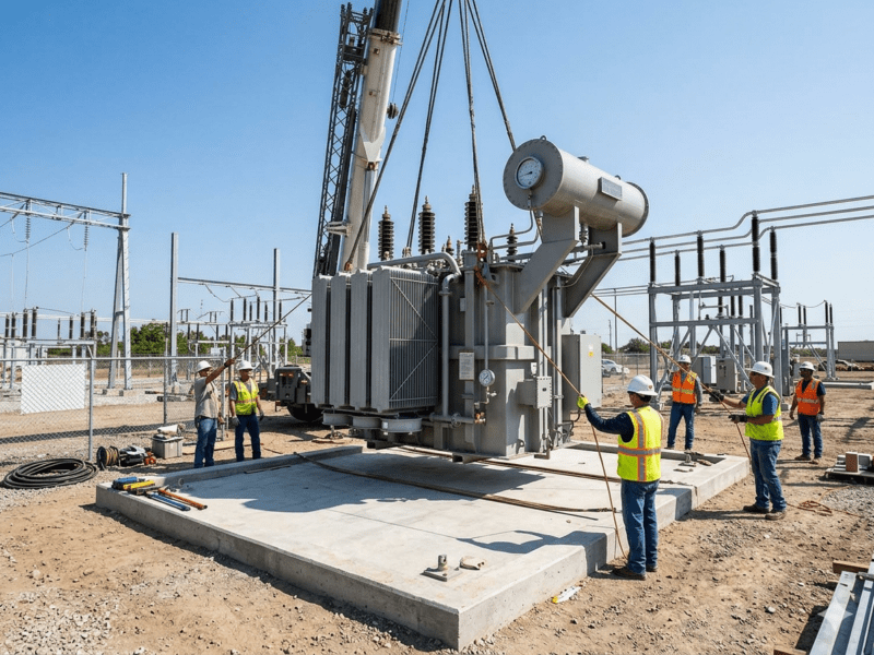
Positioning the transformer on the foundation requires careful execution.
Lifting must use proper attachment points. Transformers have designated lifting lugs or points. Use only these designated points – attaching cables elsewhere can damage the tank or cause the transformer to shift during lifting. Verify lifting lug condition before applying load.
Crane capacity must exceed the transformer weight with appropriate safety margins. Verify crane capacity, boom length, and reach for the specific lift. The crane operator should be experienced with heavy equipment lifting.
Guide the transformer carefully into position. Use tag lines controlled by workers to prevent swinging or rotation during the lift. Lower the transformer slowly, making fine adjustments to align with the foundation.
Check levelness immediately after setting. Use precision levels to verify the transformer is level in both directions. If adjustment is needed, lift the transformer slightly and adjust shims or the foundation surface. Never drive shims under a set transformer – the impact can damage internal components.
Roller and rail installations require additional steps. For transformers designed to roll into position, verify the rails are properly aligned and level. The transformer should roll smoothly into position. Secure the transformer with anchors after positioning.
Oil Processing (For Oil-Immersed Transformers)
Large transformers often ship with oil either removed or at reduced levels. Oil processing ensures proper insulation and cooling.
Oil filling procedures depend on transformer size and shipping configuration. Smaller transformers might ship oil-filled and ready for service. Larger units might ship with oil in separate tanks or drums. Follow manufacturer instructions for the specific situation.
Oil quality verification is essential before filling or energizing. Test the oil for dielectric strength, moisture content, acidity, and other parameters specified by the manufacturer. Oil that doesn’t meet specifications requires treatment or replacement.
Vacuum filling is standard practice for large transformers. The transformer tank is evacuated to remove air and moisture, then filled with oil under vacuum. This process ensures complete impregnation of insulation with oil and minimizes air bubbles that could cause partial discharge.
Hot oil circulation after filling removes residual moisture and ensures uniform oil temperature. This process might continue for several hours or days depending on transformer size and conditions.
Final oil tests verify proper processing. Dielectric strength, moisture content, dissolved gas analysis, and other tests confirm the oil is suitable for energization.
Electrical Connections
Making electrical connections correctly ensures safe, reliable operation.
High-voltage connections require appropriate cable or bus. Cable connections must use properly sized cable rated for the voltage and current. Cable terminations must be appropriate for the bushing type and cable insulation. Bus connections must be properly sized and supported.
Low-voltage connections similarly require appropriate sizing. The low-voltage side typically carries higher current than the high-voltage side, requiring larger conductors. Proper termination techniques ensure reliable connections with minimal heating.
Tightening torque is critical for all electrical connections. Loose connections cause heating, which worsens the connection and eventually causes failure. Use a torque wrench and follow manufacturer specifications for all connection hardware.
Phase identification and rotation must be correct. Verify phase sequence matches between supply and load. Incorrect phase rotation can damage motors and other rotating equipment. Use appropriate test equipment to verify phase rotation before energizing loads.
Neutral grounding must be correct for the system configuration. The neutral point might be solidly grounded, resistance grounded, or ungrounded depending on system design. Verify that the transformer neutral connection matches the system design.
Grounding Installation
Proper grounding provides safety and enables correct protection system operation.
Grounding conductor connections must be properly made. Connect the transformer tank and neutral (if applicable) to the grounding grid or grounding electrode system. Use appropriately sized grounding conductors – undersized grounding conductors cannot safely carry fault currents.
Ground resistance must be low enough for effective fault current return. Measure ground resistance and verify it meets applicable standards and system design requirements. High ground resistance reduces protection system effectiveness and creates safety hazards.
Grounding grid connections must be secure and corrosion-resistant. Use proper exothermic welding, compression connectors, or approved mechanical connectors for grounding grid connections. Protect connections from corrosion with appropriate coatings or encapsulation.
Multiple grounding points improve reliability and safety. In addition to the main grounding connection, bond all metallic structures, fences, and equipment within the substation area. This equipotential bonding prevents dangerous voltage differences during fault conditions.
Cooling System Installation
Transformer cooling systems require proper installation to function correctly.
Radiators and cooling fans (for oil-immersed transformers) must be properly installed and connected. If radiators ship separately, mount them according to manufacturer instructions. Connect oil piping and verify no leaks. Install cooling fans and connect power supplies.
Forced-air cooling systems (for dry-type transformers) require proper ventilation. Verify adequate air flow through the transformer enclosure. Install cooling fans if provided and connect power supplies.
Temperature sensors and monitoring systems must be correctly installed and connected. Oil temperature indicators, winding temperature indicators, and ambient temperature sensors provide critical monitoring data. Connect these to monitoring systems and SCADA as required.
Control power for cooling systems must be correctly wired. Cooling fans, pumps, and control systems require reliable power. Verify control power connections and protection.
Protection and Control Wiring
Protection and control systems require careful wiring to function correctly.
Current transformers (CTs) must be correctly connected. CT polarity and ratio must match the protection system requirements. Verify CT connections with current injection testing. Never open-circuit a CT secondary – the resulting voltage can be lethal.
Voltage transformers (VTs) must be correctly connected for protection and metering. Verify VT ratios and connections. Protection systems rely on accurate voltage signals.
Protection relay connections must be verified before energization. Test each protection function with secondary injection to verify correct operation. Verify trip paths from relays to circuit breakers.
Control circuits for tap changers, cooling systems, and other accessories must be correctly wired and tested. Verify that control switches and indicators function correctly. Test automatic control functions.
SCADA and monitoring connections enable remote operation and monitoring. Connect analog signals, status contacts, and control outputs to SCADA systems. Verify communication with SCADA before energizing.
Testing and Commissioning
Comprehensive testing verifies proper installation before energization.
Insulation resistance testing (Megger testing) verifies winding insulation integrity. Test between windings and from each winding to ground. Compare results to manufacturer specifications and previous test results. Low insulation resistance indicates moisture, contamination, or damage.
Winding resistance testing verifies proper connections and identifies potential problems. Measure each phase resistance and verify balance between phases. High resistance or imbalance indicates connection problems or internal faults.
Turns ratio testing verifies correct voltage transformation. Apply low voltage to the primary and measure secondary voltage. The ratio should match nameplate specification. Incorrect ratio indicates wrong connections or internal problems.
No-load loss testing at reduced voltage provides a baseline for comparison. Apply rated voltage briefly and measure excitation current. Excessive excitation current indicates core problems or winding faults.
Load tap changer testing (for transformers with OLTC) verifies proper operation through all positions. Test mechanical operation, electrical switching, and position indication. Verify that the tap changer operates smoothly without excessive heating.
Oil testing (for oil-immersed transformers) should be performed before energization. Dielectric breakdown voltage, moisture content, and dissolved gas analysis establish baseline conditions. Future test results will be compared to this baseline.
Functional testing of protection systems verifies correct operation. Test each protection function and verify correct trip outputs. Test alarm functions and monitoring systems.
Energization
Energizing the transformer requires careful preparation and execution.
Pre-energization checklist should be completed. Verify all tests are satisfactory, all connections are complete and tight, all protection systems are operational, and all personnel are clear of the equipment.
One-minute energization at rated voltage is a standard practice. Energize the transformer at rated voltage and monitor for one minute. Listen for unusual sounds, check for unusual vibrations, monitor temperatures and currents. This test identifies problems that might not appear during low-voltage testing.
Monitor for 24 hours after energization. Watch for oil leaks, unusual sounds, temperature rises, or other abnormalities. Check temperatures and pressures periodically. If problems appear, de-energize and investigate before proceeding to full operation.
Load application should be gradual. Apply load in steps, monitoring transformer response at each level. Watch for heating, voltage regulation, and cooling system operation. Gradual loading allows detection of problems before they cause damage.
Final documentation should be completed. Record all test results, settings, and observations. Complete installation records for future reference. Provide documentation to facility operations and maintenance personnel.
Documentation and Training
Complete documentation supports long-term reliable operation.
Installation records document what was done and what was found. Include test results, settings, any adjustments made, and observations during installation. These records provide baseline information for future maintenance and troubleshooting.
Operation and maintenance manuals should be provided to appropriate personnel. Ensure maintenance staff understand the transformer, its protection systems, and required maintenance procedures.
Training for operators and maintenance personnel ensures proper ongoing care. Cover normal operation, emergency procedures, and routine maintenance requirements. Well-trained personnel prevent problems and respond correctly when issues arise.
Spare parts inventory should be established. Identify critical spares and ensure they are available. Common spares include gaskets, fuses, and protection relay components.
Safety Considerations
Transformer installation involves multiple hazards requiring appropriate safety measures.
Electrical hazards are present throughout the installation. Establish and maintain proper clearances from energized equipment. Use appropriate personal protective equipment (PPE). Follow lockout/tagout procedures when working on equipment that could be energized.
Mechanical hazards exist during lifting and positioning. Keep personnel clear of suspended loads. Use proper rigging techniques. Ensure crane operations follow safety standards.
Chemical hazards are present with oil-filled transformers. Oil can cause skin irritation and environmental contamination. Use appropriate PPE when handling oil. Contain and clean up any spills immediately.
Confined space hazards might exist in underground installations or large transformers. Evaluate for confined space entry requirements. Provide appropriate ventilation and monitoring.
Working at height might be required during installation. Use fall protection when working above ground level. Ensure ladders and scaffolding meet safety standards.
Conclusion
Proper transformer installation is a systematic process requiring careful planning, precise execution, and thorough testing. Each step builds on previous steps – errors in early stages compound through later work. Taking time to do installation correctly prevents problems that could shorten transformer life or cause failure.
This guide provides general procedures applicable to most transformer installations. Always follow manufacturer-specific instructions for your particular equipment. When in doubt, consult with the manufacturer or experienced professionals.
The effort invested in proper installation pays dividends through decades of reliable transformer operation. A well-installed transformer provides safe, efficient service with minimal maintenance requirements. Rushing installation or cutting corners saves time initially but costs far more over the transformer’s lifetime.